PFA/FEP Lined Butterfly Valve

LINED BUTTERFLY VALVES
The lined butterfly valves bi-directional flow is possible at maxmium operating pressure. Since the valve port corresponds to the piping diameter, a high flow capacity is guaranteed.
▪It features ease of maintenance, repeatable on-off, long life durability.
▪The concentric design is commonly used in the power generation, brewing, water and food industries and suitable for both gaseous and liquid service. Typically applied in chemical/petrochemical process, food and beverage, and pulp and paper etc.
▪ Lining material: PTFE, PFA, FEP, PO etc.
▪Connection type: wafer, flange, lug etc.
▪Operation methods: manual, worm gear, electric, pneumatic and hydraulic actuator.
▪The lined butterfly valves are available as per the needs of applications in additional sizes and other than standard material.
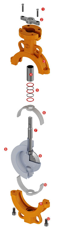
Material Specification
|
 |
||||||||||||||||||||||||||||||||||||||||||||||||||||||||||||||||||||||||||||||||||||||||||||||||||||||||||||||||||||||
Technical Specification
Note: Test standard refers general valve standard, high pressure should be customized for processing.
Note:
◆The disc should be opened from angle 5-10°if not working.
◆ The valve should be stocked indoor, and the prior temperature range is 0-25°C(40-80°F).
◆ If stock in house, the valve should open and close every three month.
◆To make sure no heavy loading on valve when transported and being stocked.
◆ It is better to install lined butterfly valve in vertical position and make the actuator directly installed in the upside of butterfly valve, generally no inversion installed.
◆ Lined butterfly valve when connected to check valve or pump, an expansion joint will be needed to make sure the adjacent equipment won’t be affected.
◆When install the lined butterfly valve, the pipe should focus on center, and it will lead the disc external diameter impacting the inner diameter
of pipe, causing the damage of disc edge, resulting in the torque increasing and causing leaking.
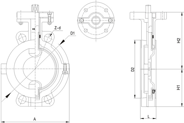
HG/T 20592/ASME B16.5(Unit:mm)
| DN | NPS | L | PN10 | PN16 | Class150 | D2 | H1 | H2 | A | |||
| D1 | Z-d | D1 | Z-d | D1 | Z-d | |||||||
| 50 | 2 | 43 | 125 | 4-18 | 125 | 4-18 | 120.5 | 4-19 | 94 | 70 | 112 | 130 |
| 65 | 2 1/2 | 46 | 145 | 4-18 | 145 | 4-18 | 139.5 | 4-19 | 110 | 80 | 125 | 150 |
| 80 | 3 | 46 | 160 | 8-18 | 160 | 8-18 | 152.5 | 4-19 | 128 | 89 | 135 | 160 |
| 100 | 4 | 52 | 180 | 8-18 | 180 | 8-18 | 190.5 | 8-19 | 150 | 105.5 | 142 | 180 |
| 125 | 5 | 56 | 210 | 8-18 | 210 | 8-18 | 216 | 8-22 | 180 | 121 | 165 | 215 |
| 150 | 6 | 56 | 240 | 8-22 | 240 | 8-22 | 241.5 | 8-22 | 205 | 145 | 180 | 242 |
| 200 | 8 | 60 | 295 | 8-22 | 295 | 12-22 | 298.5 | 8-22 | 260 | 177 | 228 | 295 |
| 250 | 10 | 68 | 350 | 12-22 | 355 | 12-26 | 362 | 12-25 | 310 | 205 | 278 | 356 |
| 300 | 12 | 78 | 400 | 12-22 | 410 | 12-26 | 432 | 12-25 | 365 | 235 | 295 | 405 |
| 350 | 14 | 78 | 460 | 16-22 | 470 | 16-26 | 476 | 12-29 | 425 | 260 | 341 | 466 |
| 400 | 16 | 102 | 515 | 16-26 | 525 | 16-30 | 540 | 16-29 | 476 | 299 | 390 | 495 |
| 450 | 18 | 114 | 565 | 20-26 | 585 | 20-30 | 578 | 16-32 | 520 | 320 | 442 | 630 |
| 500 | 20 | 127 | 620 | 20-26 | 650 | 20-33 | 635 | 20-32 | 566 | 352.5 | 470 | 670 |
Note: For more size please consult factory.
drawings:

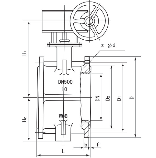
HG/T 20592(Unit:mm)
| DN | NPS | L1 Wafer |
L2 Flange |
PN10 | PN16 | D2 | H1 | H2 | A | ||||
| D | D1 | Z-d | D | D1 | Z-d | ||||||||
| 50 | 2 | 43 | 108 | 165 | 125 | 4-18 | 165 | 125 | 4-18 | 94 | 70 | 112 | 130 |
| 65 | 2 1/2 | 46 | 112 | 185 | 145 | 8-18 | 185 | 145 | 8-18 | 110 | 80 | 125 | 150 |
| 80 | 3 | 46 | 114 | 200 | 160 | 8-18 | 200 | 160 | 8-18 | 128 | 90 | 135 | 160 |
| 100 | 4 | 52 | 127 | 220 | 180 | 8-18 | 220 | 180 | 8-18 | 150 | 105 | 142 | 180 |
| 125 | 5 | 56 | 140 | 250 | 210 | 8-18 | 250 | 210 | 8-18 | 180 | 120 | 165 | 215 |
| 150 | 6 | 56 | 140 | 285 | 240 | 8-22 | 285 | 240 | 8-22 | 205 | 133 | 180 | 242 |
| 200 | 8 | 60 | 152 | 340 | 295 | 8-22 | 340 | 295 | 12-22 | 260 | 172 | 228 | 295 |
| 250 | 10 | 68 | 165 | 395 | 350 | 12-22 | 405 | 355 | 12-26 | 310 | 205 | 278 | 356 |
| 300 | 12 | 78 | 178 | 445 | 400 | 12-22 | 460 | 410 | 12-26 | 365 | 235 | 295 | 405 |
| 350 | 14 | 78 | 190 | 505 | 460 | 16-22 | 520 | 470 | 16-26 | 425 | 260 | 341 | 466 |
| 400 | 16 | 102 | 216 | 565 | 515 | 16-26 | 580 | 525 | 16-30 | 476 | 290 | 390 | 495 |
| 450 | 18 | 114 | 222 | 615 | 565 | 20-26 | 640 | 585 | 20-30 | 520 | 320 | 442 | 630 |
| 500 | 20 | 127 | 229 | 670 | 620 | 20-26 | 715 | 650 | 20-33 | 566 | 355 | 470 | 670 |
| 600 | 24 | 154 | 267 | 780 | 725 | 20-30 | 840 | 770 | 20-36 | 685 | 420 | 520 | 825 |
| 700 | 28 | 165 | 292 | 895 | 840 | 24-30 | 910 | 840 | 24-36 | 770 | 500 | 590 | 895 |
| 800 | 32 | 190 | 318 | 1015 | 950 | 24-33 | 1025 | 950 | 24-39 | B75 | 550 | 650 | 1015 |
| 900 | 36 | 203 | 330 | 1115 | 1050 | 28-33 | 1125 | 1050 | 28-39 | 980 | 580 | 645 | 1115 |
| 1000 | 40 | 216 | 410 | 1230 | 1160 | 28-36 | 1255 | 1170 | 28-42 | 1080 | 780 | 670 | 1230 |
| 1200 | 48 | 254 | 470 | 1455 | 1380 | 32-39 | 1485 | 1390 | 32-48 | 1280 | B70 | 775 | 1455 |
| 1400 | 56 | 279 | 530 | 1675 | 1590 | 36-42 | 1685 | 1590 | 36-48 | 1480 | 980 | 875 | 1675 |
| 1600 | 64 | 318 | 600 | 1915 | 1820 | 40-48 | 1930 | 1820 | 40-56 | 1690 | 1100 | 980 | 1915 |
| 1800 | 72 | 356 | 670 | 2115 | 2020 | 44-48 | 2130 | 2020 | 44-56 | 1890 | 2115 | ||
| 2000 | 80 | 406 | 760 | 2325 | 2230 | 48-48 | 2345 | 2230 | 48-62 | 2090 | 2325 | ||
Note: For more size please consult factory.
drawings:
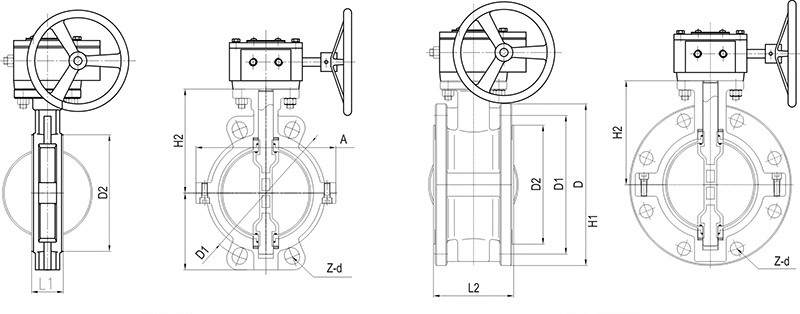
ASME B16.5 /JIS B2220(Unit:mm)
| DN | NPS | L1 Wafer |
L2 Flange |
ANSI 150Lb | JIS 10K | D2 | H1 | H2 | A | ||||
| D | D1 | Z-d | D | D1 | Z-d | ||||||||
| 50 | 2 | 43 | 108 | 150 | 120.5 | 4-19 | 155 | 120 | 4-19 | 94 | 70 | 112 | 130 |
| 65 | 2 1/2 | 46 | 112 | 180 | 139.5 | 4-19 | 175 | 140 | 4-19 | 110 | 80 | 125 | 150 |
| 80 | 3 | 46 | 114 | 190 | 152.5 | 4-19 | 185 | 150 | 8-19 | 128 | 90 | 135 | 160 |
| 100 | 4 | 52 | 127 | 230 | 190.5 | 8-19 | 210 | 175 | 8-19 | 150 | 105 | 142 | 180 |
| 125 | 5 | 56 | 140 | 255 | 216 | 8-22 | 250 | 210 | 8-23 | 180 | 120 | 165 | 215 |
| 150 | 6 | 56 | 140 | 280 | 241.5 | 8-22 | 280 | 240 | 8-23 | 205 | 133 | 180 | 242 |
| 200 | 8 | 60 | 152 | 345 | 298.5 | 8-22 | 330 | 290 | 12-23 | 260 | 172 | 228 | 295 |
| 250 | 10 | 68 | 165 | 405 | 362 | 12-25 | 400 | 355 | 12-25 | 310 | 205 | 278 | 356 |
| 300 | 12 | 78 | 178 | 485 | 432 | 12-25 | 445 | 400 | 16-25 | 365 | 235 | 295 | 405 |
| 350 | 14 | 78 | 190 | 535 | 476 | 12-29 | 490 | 445 | 16-25 | 425 | 260 | 341 | 466 |
| 400 | 16 | 102 | 216 | 595 | 540 | 16-29 | 560 | 510 | 16-27 | 476 | 290 | 390 | 495 |
| 450 | 18 | 114 | 222 | 635 | 578 | 16-32 | 620 | 565 | 20-27 | 520 | 320 | 442 | 630 |
| 500 | 20 | 127 | 229 | 700 | 635 | 20-32 | 675 | 620 | 20-27 | 566 | 355 | 470 | 670 |
| 600 | 24 | 154 | 267 | 815 | 749.5 | 20-35 | 795 | 730 | 24-33 | 685 | 420 | 520 | 825 |
| 700 | 28 | 165 | 292 | 927 | 864 | 24-35 | 905 | 840 | 24-33 | 770 | 500 | 590 | 927 |
| 800 | 32 | 190 | 318 | 1060 | 978 | 28-35 | 1020 | 950 | 28-33 | 875 | 550 | 650 | 1060 |
| 900 | 36 | 203 | 330 | 1168 | 1086 | 28-35 | 1120 | 1050 | 28-33 | 980 | 580 | 645 | 1168 |
| 100 | 40 | 216 | 410 | 1289 | 1200 | 28-41 | 1080 | 780 | 670 | 1289 | |||
| 1200 | 48 | 254 | 470 | 1500 | 1422 | 32-41 | 1280 | 870 | 775 | 1500 | |||
| 1400 | 56 | 279 | 530 | 1746 | 1651 | 36-41 | 1480 | 980 | 875 | 1746 | |||
PTFE lined Lug Type Butterfly Valve

PTFE lined Lug Type Butterfly Valve
The lined butterfly valves bi-directional flow is possible at maxmium operating pressure. Since the valve port corresponds to the piping diameter, a high flow capacity is guaranteed.
▪It features ease of maintenance, repeatable on-off, long life durability.
▪The concentric design is commonly used in the power generation, brewing, water and food industries and suitable for both gaseous and liquid service. Typically applied in chemical/petrochemical process, food and beverage, and pulp and paper etc.
▪ Lining material: PTFE, PFA, FEP, PO etc.
▪Connection type: wafer, flange, lug etc.
▪Operation methods: manual, worm gear, electric, pneumatic and hydraulic actuator.
▪The lined butterfly valves are available as per the needs of applications in additional sizes and other than standard material.
Material Specification
|
|||||||||||||||||||||||||||||||||||||||||||||||||||||
Technical Specification
| Design & Manufacture Standard | HG/T 3704, GB/T 12238 | API 6D8 | ||
| Face-to-face Dimension | HG/T 3704, GB/T 12221 | ASMEB16.10 | ||
| Flange Standard | HG/T 20592, GB/T 9119 | ASME B16.5, JIS B2220 | ||
| Inspection and Test Standard | G B/T 13927, J B/T 9092 | API 598 | ||
| Nominal Diameter(MPa) | DN50~DN1600 | 2″~64″ | ||
| Nominal Pressure(MPa) | 1 | 1.5 | 150Lb | |
| Pressure Test(MPa) | Shell Test | 1.5 | 1.5 | 1.5 |
| High Pressure Sealing | 1.1 | 1.1 | 1 . 1 | |
| Low Pressure Sealing | 0.6 | 0.6 | 0.6 | |
| Temperature Range(℃) | PTFE: 30~180 PFA: 30~200 FEP: 30~150 G×PO: 10~80 | |||
| Applicable medium | Strong corrosive medium i.e. hydrochloric acid, Nitric acid, Hydrofluoric acid, Liquid chlorine, Sulfuric Acid and Aqua regia etc. | |||
Note: Test standard refers general valve standard, high pressure should be customized for processing.
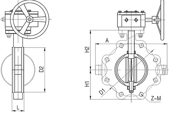
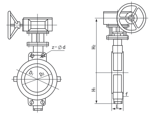
HG/T 20592 (Unit:mm)
| DN | NPS | L | PN1.0MPa | PN1.6MPa | D2 | H1 | H2 | A | ||||
| D | D1 | Z-M | D | D1 | Z-M | |||||||
| 50 | 2 | 43 | 165 | 125 | 4-M16 | 165 | 125 | 4-M16 | 90 | 70 | 112 | 96 |
| 65 | 2 1/2 | 46 | 185 | 145 | 4-M16 | 185 | 145 | 4-M16 | 110 | 80 | 125 | 112 |
| 80 | 3 | 46 | 200 | 160 | 8-M16 | 200 | 160 | 8-M16 | 130 | 89 | 135 | 130 |
| 100 | 4 | 52 | 220 | 180 | 8-M16 | 220 | 180 | 8-M16 | 148 | 105.5 | 142 | 150 |
| 125 | 5 | 56 | 250 | 210 | 8-M16 | 250 | 210 | 8-M16 | 181 | 121 | 165 | 178 |
| 150 | 6 | 56 | 285 | 240 | 8-M20 | 285 | 240 | 8-M20 | 202 | 145 | 180 | 206 |
| 200 | 8 | 60 | 340 | 295 | 8-M20 | 340 | 295 | 12-M20 | 263 | 177 | 228 | 260 |
| 250 | 10 | 68 | 395 | 350 | 12-M20 | 405 | 355 | 12-M24 | 313 | 205 | 278 | 317 |
| 300 | 12 | 78 | 445 | 400 | 12-M20 | 460 | 410 | 12-M24 | 368 | 235 | 295 | 367 |
| 350 | 14 | 78 | 505 | 460 | 16-M20 | 520 | 470 | 16-M24 | 415 | 260 | 341 | 466 |
| 400 | 16 | 102 | 565 | 515 | 16-M24 | 580 | 525 | 16-M27 | 484 | 299 | 390 | 495 |
| 450 | 18 | 114 | 615 | 565 | 20-M24 | 640 | 585 | 20-M27 | 519 | 320 | 442 | 630 |
| 500 | 20 | 127 | 670 | 620 | 20-M24 | 715 | 650 | 20-M30 | 569 | 352.5 | 470 | 694 |
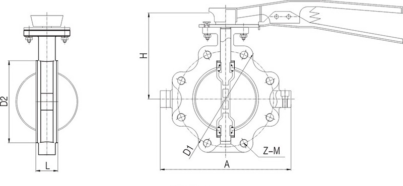
ASME B16.5 / JIS B2220 (Unit:mm)
| DN | NPS | L | PN1.0MPa | PN1.6MPa | D2 | H1 | H2 | A | ||||
| D | D1 | Z-M | D | D1 | Z-M | |||||||
| 50 | 2 | 43 | 150 | 120.5 | 4-M16 | 155 | 120 | 4-M16 | 90 | 70 | 112 | 96 |
| 65 | 2 1/2 | 46 | 180 | 139.5 | 4-M16 | 175 | 140 | 4-M16 | 110 | 80 | 125 | 112 |
| 80 | 3 | 46 | 190 | 152.5 | 4-M16 | 185 | 150 | 8-M16 | 130 | 89 | 135 | 130 |
| 100 | 4 | 52 | 230 | 190.5 | 8-M16 | 210 | 175 | 8-M16 | 148 | 105.5 | 142 | 150 |
| 125 | 5 | 56 | 255 | 216 | 8-M20 | 250 | 210 | 8-M20 | 181 | 121 | 165 | 178 |
| 150 | 6 | 56 | 280 | 241.5 | 8-M20 | 280 | 240 | 8-M20 | 202 | 145 | 180 | 206 |
| 200 | 8 | 60 | 345 | 298.5 | 8-M20 | 330 | 290 | 12- M20 | 263 | 177 | 228 | 260 |
| 250 | 10 | 68 | 405 | 362 | 12-M24 | 400 | 355 | 12-M22 | 313 | 205 | 278 | 317 |
| 300 | 12 | 78 | 485 | 432 | 12-M24 | 445 | 400 | 16-M22 | 368 | 235 | 295 | 367 |
| 350 | 14 | 78 | 535 | 476 | 12-M27 | 490 | 445 | 16-M22 | 415 | 260 | 341 | 466 |
| 400 | 16 | 102 | 595 | 540 | 16-M27 | 560 | 510 | 16-M24 | 484 | 299 | 390 | 495 |
| 450 | 18 | 114 | 635 | 578 | 16-M30 | 620 | 565 | 20-M24 | 519 | 320 | 442 | 630 |
| 500 | 20 | 127 | 700 | 635 | 20-M30 | 675 | 620 | 20-M24 | 569 | 352.5 | 470 | 694 |
PTFE lined Butterfly Valve

PTFE lined butterfly valve
The lined butterfly valves bi-directional flow is possible at maxmium operating pressure. Since the valve port corresponds to the piping diameter, a high flow capacity is guaranteed.
▪It features ease of maintenance, repeatable on-off, long life durability.
▪The concentric design is commonly used in the power generation, brewing, water and food industries and suitable for both gaseous and liquid service. Typically applied in chemical/petrochemical process, food and beverage, and pulp and paper etc.
▪ Lining material: PTFE, PFA, FEP, PO etc.
▪Connection type: wafer, flange, lug etc.
▪Operation methods: manual, worm gear, electric, pneumatic and hydraulic actuator.
▪The lined butterfly valves are available as per the needs of applications in additional sizes and other than standard
Material Specification
|
|||||||||||||||||||||||||||||||||||||||||||||||||||||
Technical Specification
| Design & Manufacture Standard | HG/T 3704, GB/T 12238 | API 6D8 | ||
| Face-to-face Dimension | HG/T 3704, GB/T 12221 | ASMEB16.10 | ||
| Flange Standard | HG/T 20592, GB/T 9119 | ASME B16.5, JIS B2220 | ||
| Inspection and Test Standard | G B/T 13927, J B/T 9092 | API 598 | ||
| Nominal Diameter(MPa) | DN50~DN1600 | 2″~64″ | ||
| Nominal Pressure(MPa) | 1 | 1.5 | 150Lb | |
| Pressure Test(MPa) | Shell Test | 1.5 | 1.5 | 1.5 |
| High Pressure Sealing | 1.1 | 1.1 | 1 . 1 | |
| Low Pressure Sealing | 0.6 | 0.6 | 0.6 | |
| Temperature Range(℃) | PTFE: 30~180 PFA: 30~200 FEP: 30~150 G×PO: 10~80 | |||
| Applicable medium | Strong corrosive medium i.e. hydrochloric acid, Nitric acid, Hydrofluoric acid, Liquid chlorine, Sulfuric Acid and Aqua regia etc. | |||
Note: Test standard refers general valve standard, high pressure should be customized for processing.
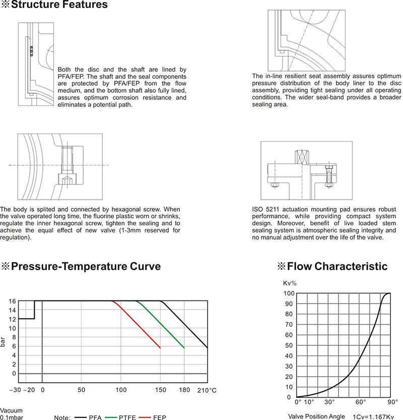
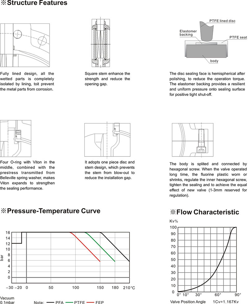
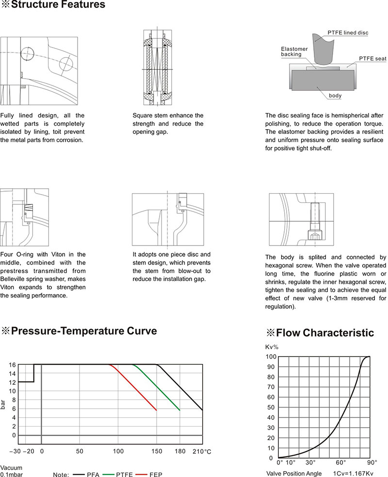
Structure Features
| DN | NPS | L1 Wafer |
L2 Flange |
PN1.0MPa | PN1.6MPa | D2 | H1 | H2 | A | ||||
| D | D1 | Z-d | D | D1 | Z-d | ||||||||
| 40 | 1 1/2 | 40 | 106 | 150 | 110 | 4-18 | 150 | 110 | 4-18 | 70 | 60 | 90 | 78 |
| 50 | 2 | 43 | 108 | 165 | 125 | 4-18 | 165 | 125 | 4-18 | 90 | 70 | 112 | 96 |
| 65 | 2 1/2 | 46 | 112 | 185 | 145 | 4-18 | 185 | 145 | 4-18 | 110 | 80 | 125 | 112 |
| 80 | 3 | 46 | 114 | 200 | 160 | 8-18 | 200 | 160 | 8-18 | 130 | 89 | 135 | 130 |
| 100 | 4 | 52 | 127 | 220 | 180 | 8-18 | 220 | 180 | 8-18 | 148 | 105.5 | 142 | 150 |
| 125 | 5 | 56 | 140 | 250 | 210 | 8-18 | 250 | 210 | 8-18 | 181 | 121 | 165 | 178 |
| 150 | 6 | 56 | 140 | 285 | 240 | 8-22 | 285 | 240 | 8-22 | 202 | 145 | 180 | 206 |
| 200 | 8 | 60 | 152 | 340 | 295 | 8-22 | 340 | 295 | 12-22 | 263 | 177 | 228 | 260 |
| 250 | 10 | 68 | 165 | 395 | 350 | 12-22 | 405 | 355 | 12-26 | 313 | 205 | 278 | 317 |
| 300 | 12 | 78 | 178 | 445 | 400 | 12-22 | 460 | 410 | 12-26 | 368 | 235 | 295 | 367 |
| 350 | 14 | 78 | 190 | 505 | 460 | 16-22 | 520 | 470 | 16-26 | 415 | 260 | 341 | 466 |
| 400 | 16 | 102 | 216 | 565 | 515 | 16-26 | 580 | 525 | 16-30 | 484 | 299 | 390 | 495 |
| 450 | 18 | 114 | 222 | 615 | 565 | 20-26 | 640 | 585 | 20-30 | 519 | 320 | 442 | 630 |
| 500 | 20 | 127 | 229 | 670 | 620 | 20-26 | 715 | 650 | 20-33 | 569 | 352.5 | 470 | 694 |
ASNE B16.5 / JIS B2220(Unit:mm)
| DN | NPS | L1 Wafer |
L2 Flange |
PN1.0MPa | PN1.6MPa | D2 | H1 | H2 | A | ||||
| D | D1 | Z-d | D | D1 | Z-d | ||||||||
| 40 | 1 1/2 | 40 | 106 | 125 | 98.5 | 4-16 | 140 | 105 | 4-19 | 70 | 60 | 90 | 78 |
| 50 | 2 | 43 | 108 | 150 | 120.5 | 4-19 | 155 | 120 | 4-19 | 90 | 70 | 112 | 96 |
| 65 | 2 1/2 | 46 | 112 | 180 | 139.5 | 4-19 | 175 | 140 | 4-19 | 110 | 80 | 125 | 112 |
| 80 | 3 | 46 | 114 | 190 | 152.5 | 4-19 | 185 | 150 | 8-19 | 130 | 89 | 135 | 130 |
| 100 | 4 | 52 | 127 | 230 | 190.5 | 8-19 | 210 | 175 | 8-19 | 148 | 105.5 | 142 | 150 |
| 125 | 5 | 56 | 140 | 255 | 216 | 8-22 | 250 | 210 | 8-23 | 181 | 121 | 165 | 178 |
| 150 | 6 | 56 | 140 | 280 | 241.5 | 8-22 | 280 | 240 | 8-23 | 202 | 145 | 180 | 206 |
| 200 | 8 | 60 | 152 | 345 | 298.5 | 8-22 | 330 | 290 | 12-23 | 263 | 177 | 228 | 260 |
| 250 | 10 | 68 | 165 | 405 | 362 | 12-25 | 400 | 355 | 12-25 | 313 | 205 | 278 | 317 |
| 300 | 12 | 78 | 178 | 485 | 432 | 12-25 | 445 | 400 | 16-25 | 368 | 235 | 295 | 367 |
| 350 | 14 | 78 | 190 | 535 | 476 | 12-29 | 490 | 445 | 16-25 | 415 | 260 | 341 | 466 |
| 400 | 16 | 102 | 216 | 595 | 540 | 16-29 | 560 | 510 | 16-27 | 484 | 299 | 390 | 495 |
| 450 | 18 | 114 | 222 | 635 | 578 | 16-32 | 620 | 565 | 20-27 | 519 | 320 | 442 | 630 |
| 500 | 20 | 127 | 229 | 700 | 635 | 20-32 | 675 | 620 | 20-27 | 569 | 352.5 | 470 | 694 |
PTFE Butterfly Valve

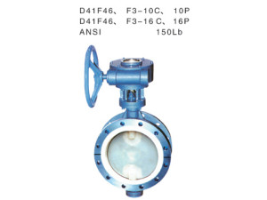
| FEP(F46) and PCTFE(F3) fluorine lined butterfly valves are applied for aqua regia, sulfuric acid, hydrochloric acid, hydrofluoric acid and various organic acid, strong acid and strong oxidizer etc in different concentration under -50℃—150℃ temperature conditions. Besides, FEP is also applied to pipelines of strong base organic solution in different concentrations and other corrosive gas and liquid medium.Main Parts and Materials: Up-and-down valve body: cast iron, cast steel, stainless steel, liner F46, F3 Seat: cast steel Disc with stem: cast iron, cast steel, stainless steel, liner F46, F3 Stuffing box: cast iron, stainless steel, liner F46, F3 Packing: F4 Gasket: silicon rubber Handle of worm gear: QT400-15 nodular cast ironTechnical Specification: Design standard: GB12238; Structure length: GB12221; Flange standard: JB/T79-94,GB9113.1-26; Inspection standard: JB/T13927; drive mode: worm gear, manual, power-driven and pneumatic
|
||||||||||||||||||||||||||||||||||||||||||||||||||||||||||||||||||||||||||||||||||||||||||||||||||||||||||||||||||||||||||||||||||||||||||||||||||||||||||||||||||||||||||||||||||||||||||||||||||||||||||||||||||||||||||||||||||||||
|
||||||||||||||||||||||||||||||||||||||||||||||||||||||||||||||||||||||||||||||||||||||||||||||||||||||||||||||||||||||||||||||||||||||||||||||||||||||||||||||||||||||||||||||||||||||||||||||||||||||||||||||||||||||||||||||||||||||
| Hot Tags: PTFE, Teflon, PTFE valve, Teflon valve, PTFE butterfly valve, Teflon butterfly valve | ||||||||||||||||||||||||||||||||||||||||||||||||||||||||||||||||||||||||||||||||||||||||||||||||||||||||||||||||||||||||||||||||||||||||||||||||||||||||||||||||||||||||||||||||||||||||||||||||||||||||||||||||||||||||||||||||||||||
PTFE Ball Valve

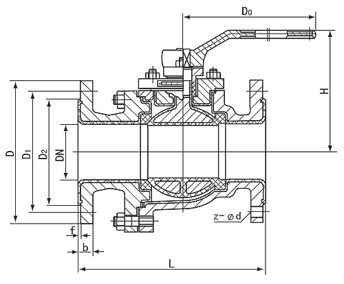
FEP(F46) and PCTFE(F3) fluorine lined ball valves are applied for aqua regia, sulfuric acid, hydrochloric acid, hydrofluoric acid and various organic acid, strong acid and strong oxidizer etc in different concentration under -50℃—150℃ temperature conditions. Besides, FEP is also applied to pipelines of strong base organic solution in different concentrations and other corrosive gas and liquid medium.
Main Parts and Materials:
Right-and-left valve body: cast iron, stainless steel, liner F46, F3
Spheroid with stem: cast iron, stainless steel, inner and outer lining F46, F3
Stuffing box: cast iron, stainless steel, liner F46, F3
Sealing ring: F4
Packing: F4
Handle: cast steel
Technical Specification:
Design standard: GB12237; Structure length: GB12221; Flange standard: JB/T79-94,GB9113.1-26; Inspection standard: JB/T9092-99; drive mode: manual, power-driven, pneumatic and worm gear
 |
Detailed Product DescriptionBall Valve
|
|||||||||||||||||||||||||||||||||||||||||||||||||||||||||||||||||||||||||||||||||||||||||||||||||||||||||||||||||||||||||||||||||||||||||||||||||||||||||||||||||||||||||||||||||
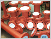
PTFE Lined Pipe and Fitting Series

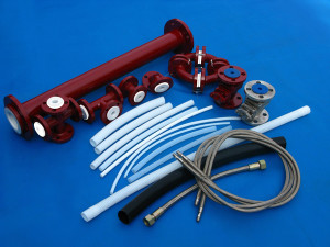
Specification of Lined Pipes and Fittings |
||||||||||||||||||||||||||||||||||||||||||||||||||||||||||||||||||||||||||||||||||||||||||||||||||||||||||||||||
1. Range |
||||||||||||||||||||||||||||||||||||||||||||||||||||||||||||||||||||||||||||||||||||||||||||||||||||||||||||||||
|
||||||||||||||||||||||||||||||||||||||||||||||||||||||||||||||||||||||||||||||||||||||||||||||||||||||||||||||||
2. Material Structure |
||||||||||||||||||||||||||||||||||||||||||||||||||||||||||||||||||||||||||||||||||||||||||||||||||||||||||||||||
|
||||||||||||||||||||||||||||||||||||||||||||||||||||||||||||||||||||||||||||||||||||||||||||||||||||||||||||||||
3. Design Requirements |
||||||||||||||||||||||||||||||||||||||||||||||||||||||||||||||||||||||||||||||||||||||||||||||||||||||||||||||||
|
||||||||||||||||||||||||||||||||||||||||||||||||||||||||||||||||||||||||||||||||||||||||||||||||||||||||||||||||
4. Detection requirements |
||||||||||||||||||||||||||||||||||||||||||||||||||||||||||||||||||||||||||||||||||||||||||||||||||||||||||||||||
|
||||||||||||||||||||||||||||||||||||||||||||||||||||||||||||||||||||||||||||||||||||||||||||||||||||||||||||||||
5. Storage, transportation and confirmation |
||||||||||||||||||||||||||||||||||||||||||||||||||||||||||||||||||||||||||||||||||||||||||||||||||||||||||||||||
|
||||||||||||||||||||||||||||||||||||||||||||||||||||||||||||||||||||||||||||||||||||||||||||||||||||||||||||||||
6. Pipe fittings A value specification |
||||||||||||||||||||||||||||||||||||||||||||||||||||||||||||||||||||||||||||||||||||||||||||||||||||||||||||||||
|
PTFE expansion joints
 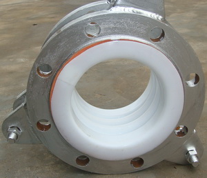
The PTFE expansion joints are unreinforced PTFE that come standard with iron 150# drill flanges. Stainless flanges are available. They are avaialable in 2, 3, or 5 convolutions of varing movements. The 2-convolution joint is sometimes referred to as a “coupling”. |
||||||||||||||||||||||||||||||||||||||||||||||||||||||||||||||||||||||||||||||||||||||||||||||||||||||||||||
|
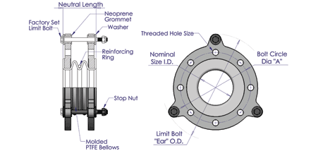 Note the change in pressure rating with temperature.
PTFE lining pipe


PTFE Lined Cross

 PTFE Lined Crosses are produced with a free sintered liner and rotatable flanges. Standard shapes are carbon steel with stainless steel available upon request. 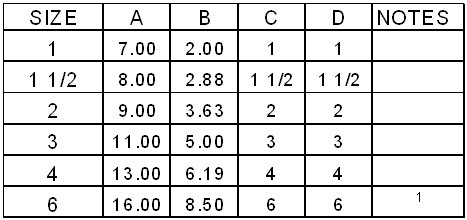 |
|
PTFE lining reducer
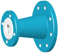
| FAB STEEL = Housing fabricated from carbon steel pipe and/or weld fittingsDI = A395 Ductile Iron – Economical Class 150 fittings with fixed flanges
CS = A216 Cast Steel – High strength steel fittings with fixed flanges Flange Material: DI = ASTM A395 Ductile Iron fixed flanges FS = Carbon Steel – ASTM A105
* Liner is PFA
|
|||||||||||||||||||||||||||||||||||||||||||||||||||||||||||||||||||||||||||||||||||||||||||||||||||||||||||||||||||||||||||||||||||||||||||||||||||||||||||||||||||||||||||||||||||||||||||||||||||||||||||||||||||||||||||||||||||||||||||||||||||||||||||||||||||||||||||||||||||||||||||||||||||||||||||||||||||||||||||||||||||||||||||||||||||||||||||||||||||||||||||||||||||||||
|
|||||||||||||||||||||||||||||||||||||||||||||||||||||||||||||||||||||||||||||||||||||||||||||||||||||||||||||||||||||||||||||||||||||||||||||||||||||||||||||||||||||||||||||||||||||||||||||||||||||||||||||||||||||||||||||||||||||||||||||||||||||||||||||||||||||||||||||||||||||||||||||||||||||||||||||||||||||||||||||||||||||||||||||||||||||||||||||||||||||||||||||||||||||||
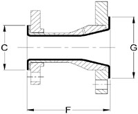 FV = Full Vacuum
PTFE Lined Tees

PTFE Lined Tees are produced with a free sintered liner and rotatable flanges.Standard shapes are carbon steel with stainless steel available upon request. 300# Tees are also available. Custom lengths are available on dimension A; amount of adjustment depends on size.
|
|
PTFE lining elbow
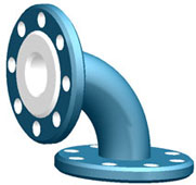
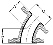
45 DEGREE ELBOWS
PTFE Lined 45 Degree Elbows are produced with a free sintered liner and rotatable flanges except where noted. Standard shapes are carbon steel with stainless steel available upon request.
| Housing Material:FAB STEEL – Housing fabricated from carbon steel pipe and/or weld fittingsDI = A395 Ductile Iron – Economical Class 150 fittings with fixed flangesFlange Material:
DI = ASTM A395 Ductile Iron FS = Carbon Steel – ASTM A105
FV = Full Vacuum
|
||||||||||||||||||||||||||||||||||||||||||||||||||||||||||||||||||||||||||||||||||||||||||||||||||||||||||||||||||||||||||||||||||||||||||||||||||||||||||||||||||||||||||||||||||
|
||||||||||||||||||||||||||||||||||||||||||||||||||||||||||||||||||||||||||||||||||||||||||||||||||||||||||||||||||||||||||||||||||||||||||||||||||||||||||||||||||||||||||||||||||
PTFE Lined Tee
- Nominal Diameter (mm/in.): DN15-DN600 (NPS 1/2- NPS 24)
- Operating temperature: -20℃ – 180℃
- Operating pressure: -0.09MPa-1.6MPa (-0.9bar-16bar)
- Pipe: Seamless steel.


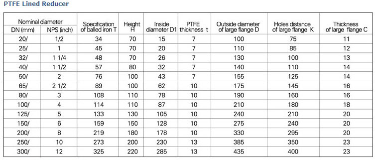
PTFE lined Reducer
- Nominal Diameter (mm/in.): DN15-DN600 (NPS 1/2- NPS 24)
- Operating temperature: -20℃ – 180℃
- Operating pressure: -0.09MPa-1.6MPa (-0.9bar-16bar)
- Pipe: Seamless steel.

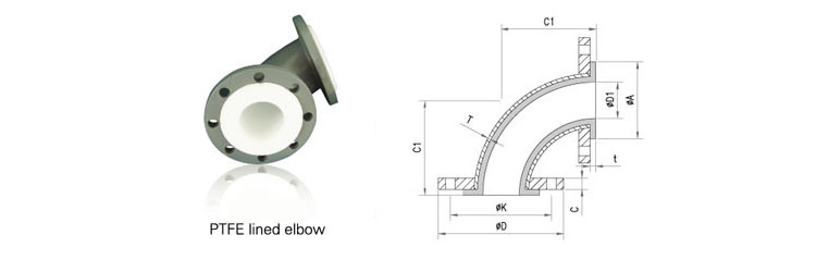
PTFE Lined Elbow
- Nominal Diameter (mm/in.): DN15-DN600 (NPS 1/2- NPS 24)
- Operating temperature: -20℃ – 180℃
- Operating pressure: -0.09MPa-1.6MPa (-0.9bar-16bar)
- Pipe: Seamless steel.
Special pieces of specific or non standard size can be manufactured on request.
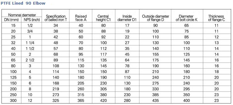
PTFE Lined Pipe

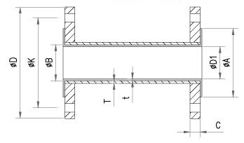 PTFE lined pipe fittings
- Nominal Diameter (mm/in.): DN15-DN600 (NPS 1/2-NPS 24)
- Operating temperature: -20℃ – 180℃
- Operating pressure: -0.09MPa-1.6MPa (-0.9bar-16bar)
- Pipe: Seamless steel.


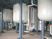
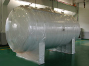
PTFE Storage Tank
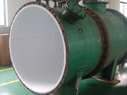
PTFE Storage Tank, Tower, Tank Liner Series
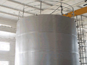
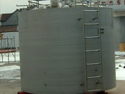
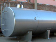
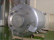
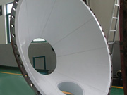
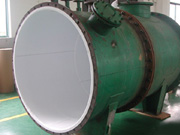
Features are as followed: Having experience and capability on PTFE liner isobaric, molding and manufacture of complete set. Ordering nonstandard vessels, division silencers, condensers, reactors, distillation towers and the like according to requirements of customers.
- Make use of inner coating and lining functions of ETFE, F46 and PVDF according to requirements of customers.