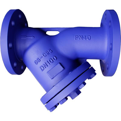
Y Type Strainer
Deaign
- Y-strainer/filter in angle pattern with body and bonnet in cast steel or carbon steel.
- Filter in staineless steel (304) or alloy steel (316).
- Standard flange or welded ends.
Standard
- Design EN 12516
- Face to face EN 558-1,
- Flange EN 1092-1
- Marking EN 19
- Pressure test EN 12266-1
- CE-mark according PED97/23, category 3
Applications
- Water, steam, oil and other fluides
- not damage the internal components.
- Uses within the all kind of industries
| Table 1. Technical specification | |
| Dimension | DN 15 to DN 400 |
| Material | Carbon steel, stainless steel |
| Pressure class | PN 16 to PN 40 |
| Temperature range | Carbon steel -10 oC to max 400oC Stainless steel to max 550oC1) |
| Connection | Flanged, Butt weld ends |
| Screen | SS304 alternative SS316 |
1) Flanged valve max 530oC
| Table 2. Pressure- temperature range, acc. to EN 1092-1 | |||||||||||||
| Material Body | PN | RT | 100 | 150 | 200 | 250 | 300 | 350 | 400 | 450 | 500 | 530 | 5501) |
| Carbon steel 1.0619 | 16 | 16.0 | 14.9 | 13,.9 | 12.4 | 11.4 | 10.3 | 9.6 | 9.2 | ||||
| Carbon steel 1.0619 | 25/40 | 40.0 | 37.3 | 34.7 | 30.2 | 28.4 | 25.8 | 24.0 | 23.1 | ||||
| Steel alloy 1.5419 | 40.0 | 40.0 | 40.0 | 38.2 | 35.6 | 30.2 | 28.4 | 26.7 | 25.8 | 18.0 | |||
| Steel alloy 1.7357 | 40.0 | 40.0 | 40.0 | 40.0 | 39.1 | 36.4 | 33.8 | 32 | 30.2 | 24.4 | 13.9 | ||
| Stainless steel CF8 | 16 | 14.7 | 12.1 | 11.0 | 10.2 | 9.6 | 9.0 | 8.7 | 8.4 | 8.1 | 7.8 | 7.6 | 7.3 |
| Stainless steel CF8M | 14.7 | 12.5 | 11.4 | 10.6 | 9.8 | 9.3 | 9.0 | 8.7 | 8.5 | 8.4 | 8.3 | 8.2 | |
| Stainless steel CF8 | 25/40 | 36.8 | 30.3 | 27.5 | 25.5 | 24.1 | 22.7 | 21.9 | 21.2 | 20.3 | 19.6 | 19.2 | 18.4 |
| Stainless steel CF8M | 36.8 | 31.3 | 28.5 | 26.4 | 24.7 | 23.4 | 22.6 | 21.8 | 21.4 | 21.0 | 20.8 | 20.7 | |
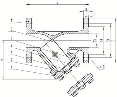
| Table 3. Material specification | |||||||
| Pos | Detail | Material | |||||
| 1 | Bolt | ASTM A 194 B7 | ASTM A 320 B8 | ASTM A 320 B8M | |||
| 2 | Sealing piece | Cu ALLOY | Cu ALLOY | Cu ALLOY | |||
| 3 | Packing | Graphite + SS304 | Graphite + SS304 | Graphite + SS316 | |||
| 4 | Bonnet | 1.0619 | 1.4308 | 1.4408 | |||
| 5 | GASKET | Graphite + SS304 | Graphite + SS304 | Graphite + SS316 | |||
| 6 | Screen | ASTM A276 304 | ASTM A276 316 | ASTM A276 304 | ASTM A276 316 | ASTM A276 304 | ASTM A276 316 |
| Table 4. Dimension and weight. PN16-PN25/40
Face to face:flanged acc. to EN 558-1 serie 1. Flange acc.to EN1092-1, type B1, Face to face:butt welded acc.to EN12982, serie 1; butt weld ends acc.to EN12627 |
||||||||||||
| DN | PN | L | D | D1 | D2 | B | N-Φd | Weightflanged | Ls | WeightBW-end | Hmax | Kv Z=4,4 |
| mm | mm | mm | mm | mm | mm | antxmm | Kg | mm | Kg | Mm | m3/h | |
| 15 | 16-25/40 | 130 | 95 | 65 | 45 | 16 | 4×14 | 2.8 | 130 | 1.9 | 85 | 6.3 |
| 20 | 150 | 105 | 75 | 58 | 18 | 4×14 | 3.8 | 150 | 2.8 | 95 | 11 | |
| 25 | 160 | 115 | 85 | 68 | 18 | 4×14 | 5.3 | 160 | 3.8 | 110 | 17.5 | |
| 32 | 180 | 140 | 100 | 78 | 18 | 4×18 | 7.2 | 180 | 4.8 | 125 | 28 | |
| 40 | 200 | 150 | 110 | 88 | 18 | 4×18 | 9 | 200 | 6.2 | 145 | 44 | |
| 50 | 230 | 165 | 125 | 102 | 20 | 4×18 | 11.8 | 230 | 8.3 | 155 | 69 | |
| 65 | 16 | 290 | 185 | 145 | 122 | 18 | 8×18 | 16.2 | 290 | 11.8 | 170 | 118 |
| 80 | 310 | 200 | 160 | 138 | 20 | 8×18 | 22.4 | 310 | 17.8 | 205 | 178 | |
| 100 | 350 | 220 | 180 | 162 | 20 | 8×18 | 35.0 | 350 | 28.6 | 230 | 270 | |
| 125 | 400 | 250 | 210 | 188 | 22 | 8×18 | 45.4 | 400 | 37.0 | 270 | 420 | |
| 150 | 480 | 285 | 240 | 218 | 22 | 8×22 | 62.0 | 480 | 51.2 | 318 | 620 | |
| 200 | 600 | 340 | 295 | 268 | 24 | 12×22 | 132.0 | 600 | 120.0 | 400 | 1150 | |
| 250 | 730 | 405 | 355 | 320 | 26 | 12×26 | 220.0 | 730 | 203.0 | 555 | 1700 | |
| 300 | 850 | 460 | 410 | 378 | 28 | 12×26 | 330.0 | 850 | 308.0 | 620 | 2500 | |
| 350 | 980 | 520 | 470 | 438 | 30 | 16×26 | 540.0 | 980 | 510.0 | 700 | 3400 | |
| 400 | 1100 | 580 | 525 | 490 | 32 | 16×30 | 830.0 | 1100 | 788.0 | 820 | 4400 | |
| 65 | 25/40 | 290 | 185 | 145 | 122 | 22 | 8×18 | 16.8 | 290 | 13.0 | 170 | 118 |
| 80 | 310 | 200 | 160 | 138 | 24 | 8×18 | 24.0 | 310 | 18.5 | 205 | 178 | |
| 100 | 350 | 235 | 190 | 162 | 26 | 8×22 | 38.8 | 350 | 29.7 | 230 | 270 | |
| 125 | 400 | 270 | 220 | 188 | 26 | 8×26 | 50.1 | 400 | 38.1 | 270 | 420 | |
| 150 | 480 | 300 | 250 | 218 | 28 | 8×26 | 68.0 | 480 | 53.4 | 318 | 620 | |
| 200 | 25 | 600 | 360 | 310 | 278 | 30 | 12×26 | 142.6 | 600 | 123.0 | 400 | 1150 |
| 250 | 730 | 425 | 370 | 335 | 32 | 12×30 | 233.4 | 730 | 208.0 | 555 | 1700 | |
| 300 | 850 | 485 | 430 | 395 | 34 | 16×30 | 350.0 | 850 | 316.0 | 620 | 2500 | |
| 350 | 980 | 555 | 490 | 450 | 38 | 16×33 | 574.0 | 980 | 540.0 | 700 | 3400 | |
| 400 | 1100 | 620 | 550 | 505 | 40 | 16×36 | 875.0 | 1100 | 835.0 | 820 | 4400 | |
| 200 | 40 | 600 | 375 | 320 | 285 | 34 | 12×30 | 153.0 | 600 | 129.0 | 400 | 1150 |
| 250 | 730 | 450 | 385 | 345 | 38 | 12×33 | 250.0 | 730 | 223.0 | 555 | 1700 | |
| 300 | 850 | 515 | 450 | 410 | 42 | 16×33 | 360.0 | 850 | 348.0 | 620 | 2500 | |
| 350 | 980 | 580 | 510 | 465 | 46 | 16×36 | 614.0 | 980 | 587.0 | 700 | 3400 | |
| 400 | 1100 | 660 | 585 | 535 | 50 | 16×39 | 940.0 | 1100 | 887.0 | 820 | 4400 | |