Factory Bends
 Factory Bends-ANSI/ASME B16.49,API 5L PSL1/PSL2
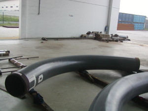
Induction Bending is a controlled means of bending pipes through the application of local heating using high frequency induced electrical power.
Originally used for the purpose of surface hardening steels, induction technology when used in pipe bending consists basically of an induction coil placed around the pipe to be bent. The induction coil heats a narrow, circumferential section of the pipe to a temperature of between 850 and 1100 degrees Celsius (dependant on the material to be formed). As the correct bending temperature range is reached, the pipe is moved slowly through the induction coil whilst the bending force is applied by a fixed radius arm arrangement.
As the bending occurs, the adjacent area forward of the heat band is water or air quenched (or may be allowed to cool naturally) thereby allowing the cool material to either side of the ‘heat band’ to retain the integrity of the original material as best as possible. This means of distortion control provides excellent dimensional accuracy and repeatability.
Achieved tolerances when forming induction bends are to some extent governed by the materials in hand and the required format of the finished product.
Although induction bending produces excellent results as far as physical properties are concerned, it must be noted that there are two important considerations required – firstly the reduction in wall thickness at the outside (extrados) of the bend and secondly the degree of ovality which is present.
The induction pipe bending process uses induction heating to produce highly accurate bends. The quality of induction bends is superior to the elbow fitting. Hydro burst tests show that spools with induction bends fail in the straight pipe and not in the bend, whereas in comparable elbow-based systems the elbow (inside radius) is always the first to burst. Stress calculations confirm this. The natural tendency to have a thicker inside wall thus proves to be advantageous and ensures that the bend exceeds the strength of the straight pipe.
Hot Induction Bends, Long Radius Piggable Bends, Induction Pipe Bending Bends Long Radius Carbon Steel Bends, Long Radius High Yield Carbon Steel Bends Long Radius Bends R-2D, R-3D, R-5D, R-6D, R-8D upto 22D Long Radius Piggable Bends R-2D, R-3D, R-5D, R-6D, R-8D upto 22D Hot Induction Long Radius Bends R-2D, R-3D, R-5D, R-6D, R-8D upto 22D API-5L Hot Induction Long Radius Bends R-2D, R-3D, R-5D, R-6D, R-8D upto 22D Induction Pipe Bending Bends 2D, 3D, 5D, 6D, 8D upto 22D Induction Long Radius Pipe Bending Bends API 5L X42, X46, X52, X56, X60, X65, X70
Induction Long Radius Pipe Bending Bends API5LX-42, X-46, X-52, X-56, X-60, X-65, X-70 Long Radius Bends 30 Deg., 45 Deg., 60 Deg., 90 Deg., 180 Deg., 360 Deg. upto 60″ Diameter Long Radius Bends in API 5L X42, API 5L X46, API 5L X52, API 5L X56, API 5L Grade B Long Radius Bends in API 5L X60, API 5L X65, API 5L X70, API 5L Grade-B Long Radius Bends in API 5L X-42, API 5L X-46, API 5L X-52, API 5L X-56, API 5L Grade B Long Radius Bends in API 5L X-60, API 5L X-65, API 5L X-70, API 5L Grade-B SA-234 WPB, WPC, WP1, WP5, WP7, WP9, WP11CL7, WP12CL1, WP22, WP91 ASTM A-860 WPHY-42, WPHY-46, WPHY-52, WPHY-56, WPHY-60, WPHY-65, WPHY-70 ASTM A-860 WPHY42, WPHY46, WPHY52, WPHY56, WPHY60, WPHY65, WPHY70 MSS SP75 WPHY 42, WPHY 46, WPHY 52, WPHY 56, WPHY 60, WPHY 65, WPHY 70 MSS SP75 WPHY42, WPHY46, WPHY52, WPHY56, WPHY60, WPHY65, WPHY70 MSS-SP-75 WPHY42, WPHY46, WPHY52, WPHY56, WHPY60, WHPY65, WPHY70 MSS-SP-75 WPHY 42, WPHY 46, WPHY 52, WPHY 56, WHPY 60, WHPY 65, WPHY 70 MSS-SP-75 WPHY-42, WPHY-46, WPHY-52, WPHY-56, WHPY-60, WHPY-65, WPHY-70
MSS SP75 WPHY42, WPHY46, WPHY52, WPHY56, WHPY60, WHPY65, WPHY70 MSS SP75 WPHY 42, WPHY 46, WPHY 52, WPHY 56, WHPY 60, WHPY 65, WPHY 70 MSSSP75 WPHY-42, WPHY-46, WPHY-52, WPHY-56, WHPY-60, WHPY-65, WPHY-70 ASTM A-234 WPB, ASTM A234 WPC, ASTM A234 WPB Seamless, ASTM A234 WPC Seamless ASTM A-234 WP1, WP11 CL1, WP11 CL3, WP12 CL1, WP22 CL1, WP22 CL3 ASTM A-234 WP5 CL1, WP5 CL3, WP9 CL1, WP9 CL3, WP91 ASTM A-403 WP304, 304L, 304H, 310S, 316, 316L, 316H, 321, 321H, 347, 347H, 317, 317L ASTM A-420 WPL3, WPL6, WPL8, WPL9 ASTM A-182 F304, F304L, F304H, F310S, F316, F316L, F316H, F321, F321H, F347, F347H, F348 ASTM A-182 F1, F11, F12, F22, F5, F9, F91, F92
ASTM A-182 F-1, F-11, F-12, F-22, F-5, F-9, F-91, F-92 ASTM A-694 F-42, ASTM A694 F-46, ASTM A694 F-52, ASTM A694 F-56 ASTM A-694 F-60, ASTM A694 F-65, ASTM A694 F-70, ASTM A694 F-80 SAE / AISI Grade 1008, 1010, 1018, 1020, 1025, 1026, 1040, 1045, 1050, 4130, 4140, 4150, 4340 AISI-4130 L-80 according to API-5CT, 75KSI according to API-6A Quenched / Hardened & Tempered SAE-4130 L-80 according to API-5CT, 75KSI according to API-6A Quenched / Hardened & Tempered AISI-4140 L-80, P-110 according to API-5CT, API6A, NACE MR-01-75 Quenched / Hardened & Tempered SAE-4140 L-80, P-110 according to API-5CT, API6A, NACE MR-01-75 Quenched / Hardened & Tempered Duplex 2205, Duplex SAF 2205, Duplex SAF2205, Duplex UNS S31803, Din 1.4462 EN 10088 F51 Duplex ASTM A182 Grade F60 / ASME SA182 Grade F60 NACE & Norsok Approved Duplex SAF2205 SANMAC, URANUS 45N, PREN=33, PREN=34, PREN=35, PREN=36 DIN 1.4462 Duplex-2205 UNS S31803 / UNS S32205 DIN-1.4462 EN 10088-3 PREN = 33, PREN = 34, PREN = 35 Super Duplex 2507, Super Duplex SAF 2507, Super Duplex SAF-2507, Super Duplex UNS S32750 F53
Super Duplex SAF 2507 UNS S32750 DIN 1.4410 EN-10088 URANUS 47N(+) PREN=41 Minimum Super Duplex UNS S32760 F-55 ASTM A182 F55 SA182 F-55 DIN 1.4501 UNS 32760 F55
Inspection & Approval Certificates : EN10204 3.1 / DIN 50049 3.1 / ISO 10474 3.1 Mill Test Certificate, NACE MR-0175 / ISO 15156, NACE MR-01-03 / NACE MR-01-75 / ISO 15156, CE Marked, European Pressure Equipment Directive PED-97/23/EC, AD-2000-W0, ASME Boiler & Pressure Vessel Code Sec.II Part A Ed. 2008, with 3.2 certificate duly Certified & Approved by LRS (Lloyd’s Register), GL (Germanischer Lloyd), BV (Bureau Veritas), DNV (Det Norske Veritas), ABS (American Bureau of Shipping), SGS, TUV, RINA, IRS, NORSOK Approved Standard M-630, M-650 Rev.3
ANSI/ASME B16.49-2001 Factory-Made Wrought Steel Buttwelding Induction Bends for Transportation and Distribution Systems
MSS SP-75 Specification for High-Test,Wrought,Butt-Welding Fittings EN 14870-1 Petroleum and natural gas industries. Induction bends, fittings and flanges for pipeline transportation systems-Part 1: Induction Bends
ISO 15590-1:2004, Petroleum and natural gas industries. Induction bends, fittings and flanges for pipeline transportation systems. Part 1. Induction bends
Total GS EP PLR 221 Fabrication of hot bends for pipelines (sweet service)
| Nominal Pipe Size in | Outside diameter O.D.(mm) | BENDING RADIUS(mm) | Angle Bending θ | Tangent Length at Each end | Wall Thickness (mm) | |||||
| 3D | 4D | 5D | 6D | 8D | 10D | |||||
| 3″ | 89 | 267 | 356 | 445 | 534 | 712 | 890 | 90°,60° 45°,30° 22.5°,or as per the choice of purchaser | 350 | Sch STD, sch10,Sch20, Sch30,Sch40, Sch80,etc. or as per the choice of purchaser |
| 4″ | 114 | 342 | 456 | 570 | 684 | 912 | 1140 | 350 | ||
| 6″ | 168 | 504 | 672 | 840 | 1008 | 1344 | 1680 | 350 | ||
| 8″ | 219 | 657 | 876 | 1095 | 1314 | 1752 | 2190 | 700 | ||
| 10″ | 273 | 819 | 1092 | 1365 | 1638 | 2184 | 2730 | 700 | ||
| 12″ | 325 | 975 | 1300 | 1625 | 1950 | 2600 | 3250 | 700 | ||
| 14″ | 356 | 1068 | 1424 | 1780 | 2136 | 2848 | 3560 | 700 | ||
| 16″ | 406 | 1218 | 1624 | 2030 | 2436 | 3248 | 4060 | 700 | ||
| 18″ | 457 | 1371 | 1828 | 2285 | 2742 | 3656 | 4570 | 1000 | ||
| 20″ | 508 | 1524 | 2032 | 2540 | 3048 | 4064 | 5080 | 1000 | ||
| 22″ | 559 | 1677 | 2236 | 2795 | 3354 | 4472 | 5590 | 1000 | ||
| 24″ | 610 | 1830 | 2440 | 3050 | 3660 | 4880 | 6100 | 1000 | ||
| 26″ | 660 | 1980 | 2640 | 3300 | 3960 | 5280 | 6600 | 1D (Outside diameter of bend)or as per the choice of purchaser |
||
| 28″ | 711 | 2133 | 2844 | 3555 | 4266 | 5688 | 7110 | |||
| 30″ | 762 | 2286 | 3048 | 3810 | 4572 | 6096 | 7620 | |||
| 32″ | 813 | 2439 | 3252 | 4065 | 4878 | 6504 | 8130 | |||
| 34″ | 864 | 2592 | 3456 | 4320 | 5184 | 6912 | 8640 | |||
| 36″ | 914 | 2742 | 3656 | 4570 | 5484 | 7312 | 9140 | |||
| 38″ | 965 | 2895 | 3860 | 4825 | 5790 | 7720 | 9650 | |||
| 40″ | 1016 | 3048 | 4064 | 5080 | 6096 | 8128 | 10160 | |||
| 42″ | 1067 | 3201 | 4268 | 5335 | 6402 | 8536 | 10670 | |||
| 44″ | 1118 | 3354 | 4472 | 5590 | 6708 | 8944 | 11180 | |||
| 46″ | 1168 | 3504 | 4672 | 5840 | 7008 | 9344 | 11680 | |||
| 48″ | 1219 | 3657 | 4876 | 6095 | 7314 | 9752 | 12190 | |||
| 50″ | 1270 | 3810 | 5080 | 6350 | 7620 | 10160 | 12700 | |||
| 52″ | 1321 | 3963 | 5284 | 6605 | 7926 | 10568 | 13210 | |||
| 54″ | 1372 | 4116 | 5488 | 6860 | 8232 | 10976 | 13720 | |||
| 56″ | 1422 | 4266 | 5688 | 7110 | 8532 | 11376 | 14220 | |||
Bend end preparation:Welding ends to be beveled as per ASME B16.25 or as per specified by purchaser. Induction Pipe Bending Standard Bend Tolerances Bend Angle:±1/2° Bend Radius:±1% Bend Plane:±1° End squareness Size NPS36″ and smaller:2.4mm(0.09″) Size Greater than NPS36″:3.0mm(0.12″)
Linear Dimensions Size Nps24″ and smaller:±5mm(0.19″) Size Greater than NPS 24″:±6mm(0.25″) Thinning: <0.10% of the bend nominal wall thickness or ≤50D/R(%)(R=bend centerline radius, D=nominal outside diameter of starter stock) or ≤0.05% of the nominal wall thickness of the matching pipe.