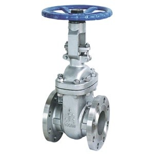
Rising Stem Gate Valves
Cast Steel Bolted Bonnet Gate Valves (Rising Stem) 150lb – 2500lb
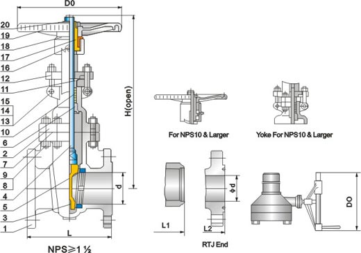
Parts and Material List
| Parts No. | Parts Name | Materials | ||||
| WCB/Trim1 | WCB/Trim5 | WCB/Trim8 | CF8/304 | CF8M/316 | ||
| 1 | Body | ASTM A216 WCB | ASTM A351 CF8 | ASTM A351 CF8M | ||
| 2 | Gasket | Soft iron+Graphite or 304+Graphite | 304+Graphite | 316+Graphite | ||
| 3 | Seat ring | A105+13Cr | A105+STL | A105+STL | ASTM A351 CF8 | ASTM A351 CF8M |
| 4 | Gate | ASTM A216 WCB+13Cr | ASTM A216WCB+STL | ASTM A216 WCB+13Cr | ASTM A351 CF8 | ASTM A351 CF8M |
| 5 | Stem | ASTM A182 F6a | ASTM A182 F304 | AST A182 F316 | ||
| 6 | Backseat bushing | ASTM A182 F6a | ASTM A351 CF8 | ASTM A351 CF8M | ||
| 7 | Packing | Graphite | Graphite | Graphite | ||
| 8 | Gland | ASTM A182 F6a | ASTM A182 F304 | ASTM A182 F316 | ||
| 9 | Gland eyebolt | ASTM A193 B7 | ASTM A193 B8 | ASTM A193 B8M | ||
| 10 | Eyebolt nut | ASTM A194 2H | ASTM A193 8 | ASTM A194 8M | ||
| 11 | Eyebolt pin | ASTM A36 | 304SS | 316ss | ||
| 12 | Gland flange | ASTM A216 WCB | ASTM A351 CF8 | ASTM A351 CF8M | ||
| 13 | Bonnet bolt | AST A193 B7 | ASTM A193 B8 | ASTM A193 B8M | ||
| 14 | Bonnet nut | ASTM A194 2H | ASTM A194 8 | ASTM A194 8M | ||
| 15 | Bonnet | ASTM A216 WCB | ASTM A351 CF8 | ASTM A351 CF8M | ||
| 16 | Nipple | Carbon steel | Carbon steel | Carbon steel | ||
| 17 | Stem nut | ASTM A439 D2 | ASTM A439 D2 | ASTM A439 D2 | ||
| 18 | Yoke sleeve nut | Carbon steel | Carbon steel | Carbon steel | ||
| 19 | Hand wheel | Ductile iron | Ductile iron | Ductile iron | ||
| 20 | Hand wheelnut | Carbon steel | Carbon steel | Carbon steel | ||
| 21 | Set screw | ASTM A193 B7 | ASTM A193 B7 | ASTM A193 B7 | ||
NOTE: The chart above only lists out some common composition of parts. We may provide other different parts material composition according to the customer’s request or the actual valve working condition.
Features
- Seal-welded seats
- Bosses for taps & bypass
- Graphite packing
- Ring Joint Bonnet gaskets Class 600-2500
- Fully guided, wedge
- Fugitive emission tested
Options
- Alternate Trims
- NACE MR-01-75
- Mounting Pads for Actuation
- Pressure Seal Bonnets Class 600-2500
- Aluminum Bronze and Bronze Trims for Marine Service
Standards
- API-600
- ANSI B16.34
- ANSI B16.10
- ANSI B16.5
- ANSI B16.25
- ANSI B16.47
- API-598
OTE: The chart above only lists out some common composition of parts. We may provide other different parts material composition according to the customer’s request or the actual valve working condition.
Structure dimensions
| CLASS/SIZE | 150 -L | 300 -L | 600 -L | 900-L | ||||
| RF | BW | RF/BW | RTJ | RF/BW | RTJ | RF/BW | RTJ | |
| 2 | 178 | 216 | 216 | 232 | 292 | 295 | 368 | 371 |
| 2 1/2 | 191 | 241 | 241 | 257 | 330 | 333 | 419 | 422 |
| 3 | 203 | 283 | 283 | 298 | 356 | 359 | 381 | 384 |
| 4 | 229 | 305 | 305 | 321 | 432 | 435 | 457 | 460 |
| 5 | 254 | 381 | 381 | 397 | 508 | 511 | 559 | 562 |
| 6 | 267 | 403 | 403 | 419 | 559 | 562 | 610 | 613 |
| 8 | 292 | 419 | 419 | 435 | 660 | 664 | 737 | 740 |
| 10 | 330 | 457 | 457 | 473 | 787 | 791 | 838 | 841 |
| 12 | 356 | 502 | 502 | 518 | 838 | 841 | 965 | 968 |
| 14 | 381 | 572 | 762 | 778 | 889 | 892 | 1029 | 1038 |
| 16 | 406 | 610 | 838 | 854 | 991 | 994 | 1130 | 1140 |
| 18 | 432 | 660 | 914 | 930 | 1092 | 1095 | ||
| 20 | 457 | 711 | 991 | 1010 | 1194 | 1200 | ||
| 24 | 508 | 813 | 1143 | 1165 | 1397 | 1407 | ||
| 26 | 559 | 864 | 1245 | 1270 | ||||
| 28 | 610 | 914 | 1346 | 1372 | ||||
| 30 | 610 | 914 | 1397 | 1422 | ||||
| 32 | 711 | 965 | 1524 | 1553 | ||||
| 34 | 762 | 1016 | 1626 | 1654 | ||||
| 36 | 711 | 1016 | 1727 | 1756 | ||||
1. Gate valve are normally used for on-off service and are not recommended for throttling service.
2. Gate valves are normally installed in horizontal pipe runs with the stem vertical. They can also be installed in vertical or horizontal pipe runs with the stem other than vertical, but may require special construction depending on valve size, service conditions and materials. WHEN PURCHASING VALVES FOR OTHER THAN NORMAL INSTALLATION, THE VALVE ORIENTATION SHOULD BE SPECIFIED.
3. Flexible or split wedges are recommended for service above 500 ℉ to avoid wedge binding due to thermal expansion. This may occur if the valve is closed when cold, and then heated to operating temperature.
4. Threaded seat rings should be lock welded to the body when used in high velocity (turbulent) or thermal cycling services to avoid loosening. Please specify.
5. After closing a gate valve with sufficient force to develop shutoff, the stem should be backed off slightly (1/8 to 1/4 turn) to relieve stem load. This will enable the stem to expand slightly without binding or damaging the valve and will not affect shutoff.